DRIFT IN TEM: CAUSES AND SOLUTIONS
Drift in TEM refers to a continuous, slow, unidirectional or cyclical movement of the sample region within the field of view during observation or imaging. It severely degrades the quality of high-resolution imaging and spectroscopic analysis (e.g., EDS).
Below are the main causes of drift and their corresponding solutions.
I. Main Causes of Drift
1. Mechanical Drift (Most Common)
- Incompletely locked specimen holder: The holder is not fully seated or the locking mechanism is loose after insertion.
- Loose specimen clamp/grid retainer: The support film or grid is not firmly pressed in the holder; electron beam or thermal effects cause creeping.
- Stage bearing or motor creep: Increased mechanical clearance after prolonged use, especially during tilting or heating.
- Deformation of O-rings on the holder: O-ring stress relaxation after insertion leads to slow positional recovery.
2. Thermal Drift
- System not thermally equilibrated: After changing holders, refilling the LN₂ dewar, or fluctuating ambient temperature, different components (pole piece, stage, holder) have different coefficients of thermal expansion.
- Electron beam heating: A high-beam current focused on one spot for too long causes localized thermal expansion of the sample or grid.
- “Bimetal” effect: Differential thermal expansion between different metals (e.g., Cu and C) at the holder tip, causing bending.
3. Electrostatic / Charging Drift
- Charge accumulation on insulating samples: Incoming electrons cannot be conducted away, building up an electrostatic field that deflects the incident beam, creating the appearance of sample movement (actually beam deflection).
- Charging of contamination layer: Hydrocarbon contaminants become polarized or charged under the beam.
4. Magnetic Field Interference
- Nearby power supplies, scanning coils, or even fluctuations in the Earth’s magnetic field cause the electron beam to shift across the sample surface, often accompanied by image distortion or jitter.
5. Sample Instability
- Shrinking or deformation of polymers and biological samples under the beam.
- Electron-beam-driven rotation or sliding of nanoparticles or 2D materials.
II. Solutions and Countermeasures
1. Proper Operation & Mechanical Stabilization
- Relock the specimen holder: Remove and reinsert the holder, ensuring the ratchet or latch clicks into place.
- Use anti-loosening specimen clamps: Choose holders with spring-loaded clamps or add a small piece of copper foil under the retainer for extra pressure.
- Allow mechanical equilibration: Wait 5–10 minutes after holder insertion for O-ring stress to relax.
2. Thermal Stabilization
- Pre-condition the system: Turn on the electron gun and lens systems for at least 30–60 minutes before inserting the sample.
- Stabilize the LN₂ cold trap: If using a cold trap/anti-contaminator, wait 20–30 minutes after filling LN₂ before observation.
- Reduce beam current: Use a smaller condenser aperture, spread the beam, or use low-dose mode.
- Pre-illuminate the sample: For thermally sensitive samples, a brief defocused beam exposure can help thermal drift stabilize faster.
3. Eliminate Charging Drift
- Deposit a conductive coating: For insulating samples, coat with a thin layer (a few nm) of carbon, gold, chromium, etc.
- Use low-voltage / low-dose mode: Reduce the accelerating voltage (e.g., to 80 kV) where possible.
- Use conductive grids: Choose Cr, Au, Ni grids, or those with conductive support films (e.g., C-flat, ultraAuFoil).
- Tilt the sample: A small tilt (e.g., ±10°) can sometimes alter the charge dissipation path.
4. Software & Hardware Compensation
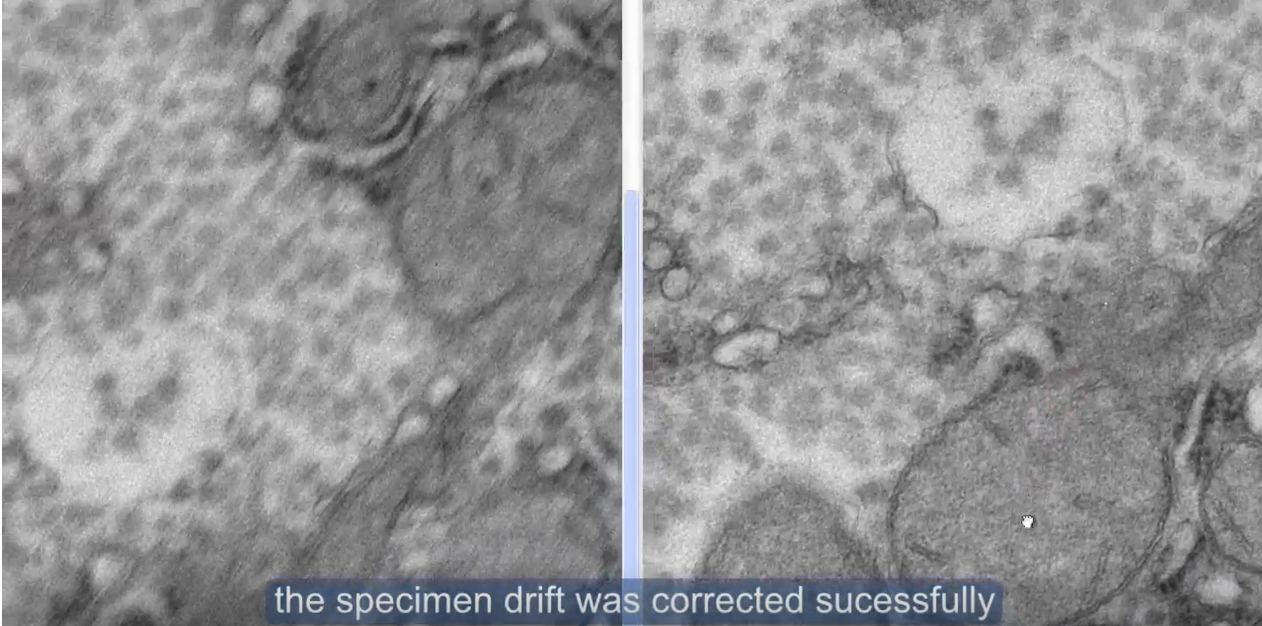
- Enable drift correction: Many modern TEM software packages (e.g., RADIUS software of EMSIS) automatically track the movement of image. Multiple frames were taken at shorter exposure time to reduce the drift effect. The software processes the multiple frames by croping each frame accordingly before integration to generate the final image.
- Use drift monitoring:Before acquiring a time series (e.g., tilt series, EDS map), turn on the software’s real-time drift display.
- Employ active vibration and magnetic field cancellation: Use a system to reduce environmental magnetic fields and vibrations.
5. Practical Experimentation Tips
- Choose a stable support film: Thicker or carbon-coated films are generally more stable than bare holey grids.
- Find an “anchor point”: Locate an edge or hole near your area of interest as a reference for manual compensation using the trackball.
- Reduce magnification: Drift appears faster at higher magnifications. Find a stable region at lower magnification first.
- Acquire rapidly: For slow drift (< 0.5 nm/s), use a fast camera (e.g., Xarosa) to acquire before drift blurs the image (e.g., < 1 second exposure).
III. Typical Troubleshooting Flowchart

IV. Final Recommendations
If the above methods fail:
- Move to a different area – Some regions are inherently unstable due to broken support film or loose particles.
- Change the specimen holder – A dedicated drift-stabilized (high-stability) holder is much more stable than a standard holder.
- Use a different TEM – Older microscopes have significantly more mechanical stage drift than newer ones equipped with piezo-driven stages.
Practical rule of thumb: In most cases, allowing sufficient time for the system to stabilize (30 minutes after holder insertion) resolves the majority of drift issues. For atomic-resolution imaging, it is recommended to wait until the residual drift rate is below 0.1 nm/s before starting acquisition.